Building Information Modelling
Project 1: BIM Applications in AEC Infographic (30%)
Introduction
This involves the study of the current applications of Building Information Modeling (BIM) in Architecture, Engineering & Construction (AEC). This project intends to expose students to the various current applications in the AEC industries, through an in-depth review of the literatures. The findings are presented in the form of an infographic.
Objective of Project
The objective of this project is as follow:
Understand the applications and research of Building Information Modeling (BIM) in Architecture, Engineering &
Construction (AEC).
Learning Outcomes of this Project
To apply understanding of Building Information Modeling and its relevance to the changing profession and
demonstrate integration of information learned in particular building technologies and building sciences.
Tasks - Methodology
1. You are to identify ONE specific area from the following and conduct a literature review based on case
studies of application/research in BIM.
2. You are to present your findings in the form of an infographic with the following contents:
• Concepts and framework of how BIM is applied in the selected field.
• Highlights of features of BIM that contributes to the applications.
• One example of case study that applied the concepts and framework of the above.
3. Your infographic must include a complete reference listadhering to APA style referencing format.
Submission Requirement
• Interim: One page A4 size topic proposal showing the title, concepts/framework of selected BIM
applications and one case study.
• Final: One printed A2 size infographic with appropriate title, visual compositions and reference list
• Submit softcopy file of the above to TIMeS.

Project 2a: Building Modeling (30%)
Introduction
The second project involves the production of Revit model of the selected architecture design using
Architectural Components such as Wall, Roof, Stairs, Floor, Curtain Wall, Doors and Windows.
Objectives of Project
The objectives of this project are as follows:
Understand and apply Revit Architecture’s modeling tools to generate a building model.
Learning Outcomes of this Project
• To learn access and build up databases to produce a simple BIM model and architectural details
complete with integrated information of materials; and their manipulation to have quick options in a
given situation.
• To use BIM as a design tool to create 3 dimensional models to analyze the aesthetics and technical
requirement.
Tasks - Methodology
1. Based on the selected architectural design, you are to generate a Revit model. The model must be
compliant withLOD200 requirements (refer Appendix 1).
2. Your Revit model must include at least TWO Revit Family components.
3. You are required to create a blog or Facebook album for public access. The Work in Progress (WIP)
print screens and test renderings must be uploaded to the above online platform REGULARLY to
show progressive evidence of the working process. It will serve as a communication and mutual
learning platform. You are encouraged to visit your peers’ WIP and give constructive comments and
suggestions.
Submission Requirement
• Submit a folder containing the Revit file and Revit Family file to TIMeS.
• Upload Work in Progress (WIP) print screens and to your WIP website
Building Modelling
 |  |  |
|---|---|---|
 |  |  |
 |  |  |
 |
Family 1 Modelling
 |  |  |
|---|---|---|
 |  |  |
 |
Family 2 Modelling
 |  |  |
|---|---|---|
 |  |  |
Family 3 Modelling
 |  |  |
|---|
Project 2b: Building Documentation (40%)
This project involves the production of building documentation drawings from the Revit model created in Project
2a, using Revit’s Documentation Components such as Sheets, Titleblock, Sections, Room Tags, Schedule and
Phasing.
Objectives of Project
The objectives of this project are as follows:
To prepare building documentation drawings, continuing from Project2.
Learning Outcomes of this Project
• To learn access and build up databases to produce a simple BIM model and architectural details
complete with integrated information of materials; and their manipulation to have quick options in a
given situation.
• To use BIM as a design tool to create 3 dimensional models to analyze the aesthetics and technical
requirement.
Tasks - Methodology
1. Using the Revit model from Project 2, you are required to prepare building documentation drawings in A1
size containing the following components:
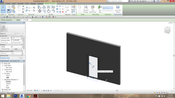
• Plans
• Elevations
• 2 Sections
• 2 Callouts on sections
• 1 Exploded isometric
• Phasing (existing, demolished, new)
• 1 Room Schedule showing area tabulation
• Perspective line renderings *(2 exteriors + 2 interiors)
*colour renderings NOT required
2. Your Revit model must comply with LOD 200 requirements (refer Appendix 1).
3. The Work in Progress (WIP) must be uploaded to the mentioned online platform to show progressive
evidence of the working process. It will serve as a communication and mutual learning platform. You are
encouraged to visit your peers’ WIP and give constructive comments and suggestions.
Submission Requirement
• Submit a folder containing the Revit file and Revit Family file to TIMeS.
• A1 size printed hardcopy.
• Upload Work in Progress (WIP) print screens and to your WIP website.
Floor Plans
1. Duplicate views if necessary.
2. Use Room (RM) to label interior spaces.
3. Use Annotate> Colour Fill to generate room legend.
4. Use Edit Scheme to modify legend colour.
5. In the Plan’s Type Properties, change Underlay to None to hide lines of lower level.
6. Enable Crop View and Show/Hide Crop Region to adjust the views.
7. Adjust Visual Style and Detail Level to suit requirements
 |  |  |
|---|---|---|
 |  |  |
 |  |  |
Furniture Layout Plans
1. Duplicate GROUND FLOOR view with detailing to keep the dimensions & etc., rename ‘GROUND FLOOR Furniture Layout’.
2. Add furnitures by using Component > Place a Component > Load Family
3. The furnitures should only appear in ‘GROUND FLOOR Furniture Layout’ view. To hide the furnitures in GROUND FLOOR view, use View > Visibility/Graphics (VG) to control visibility of the furnitures in the current view.
4. From the VG list, uncheck ‘Furniture’ under Visibility column. All furniture components will not be visible under this setting.
5. To highlight furniture components in colour, create a Filter (View > Filters ).
6. Click ‘New’ and name it as ‘Furniture Layout’. Select only ‘Furniture’ so that all furniture components will be included in this Filter.
7. Under ‘GROUND FLOOR Furniture Layout’ view, open VG (View > Visibility/Graphics). Click on the ‘Filters’ tab. Add the ‘Furniture Layout’ Filter.
8. Override the Lines colour by changing to red.
9. All furniture components will be displayed in red.
10. Repeat for ‘FIRST FLOOR Furniture Layout’ view.
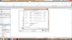
Schedules
1. Create a new Furniture Schedule: View > Schedule. Select ‘Furniture’.
2. For the Schedule Properties, add Type, Level and Count fields.
3. Key in the Sorting/Grouping settings
4. A Furniture Schedule will be generated
5. Use the same method for Door and Window Schedules with relevant Fields.
6. Customise the appearance if necessary.
 |  |  |
|---|---|---|
 |  |  |
 |  |  |
 |
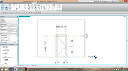
Sections
1. Create Section from plan view.
2. Modify section cutting using Split Segment if necessary.
3. Use Tag Room (RT) to label interior spaces.
4. Go to section view, inspect the model, amend joining if necessary.
5. Click on section view crop, point cursor on Vertical/Horizontal View Break to split and adjust view crop. Click ‘ResetCrop’ to disable ViewBreak.
6. For each section views, modify the view using View>Cut Profile on components such as floor and wall. This effect is view specific and won’t affect the model and other views.
7. To create hidden pad-footing, use Annotate > Masking Region to sketch.
8. Generate your own dash line spacing with Manage > Additional Settings > Line Patterns. Create new pattern
9. Create new Line Style using Manage > Additional Settings > Line Style
 | |  |
|---|---|---|
 |  |  |
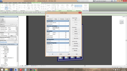
Phasing
1. Generate 3 views each (Existing, Demolish, New Construction) for plans and 3D
views.
2. Modify the Phase parameter in each view’s Type Properties (refer PHASING
SETTINGS.pdf)
3. Change the Phases settings: Manage > Phases (refer PHASING SETTINGS.pdf).
4. Change phase properties of each affected components.
 |  |  |
|---|---|---|
 |  |  |
 |  |  |